Sequence diagrams illustrate the object that participate in a use case and the messages that pass between them over time for a use case. One sequence diagram is only for one use case.
Elements of a sequence diagram
Actor
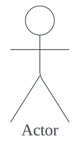 Represents the roles played by users, external equipment, or other actors.
Lifeline
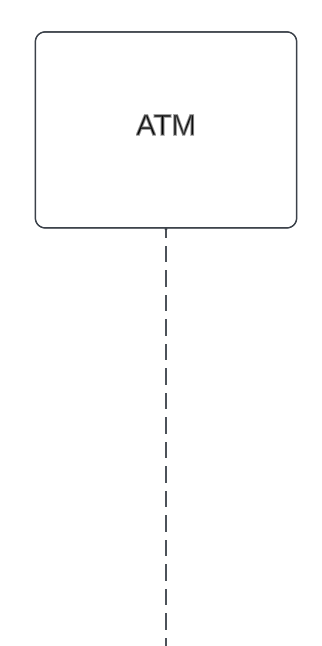 Represents an individual participant in the interaction and display the passage of time
Activation
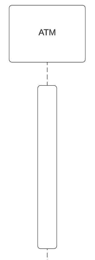 The length of the thin rectangle on the lifeline indicates the period during which the element performs an operation.
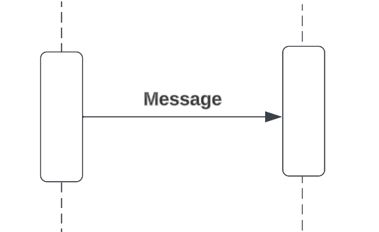
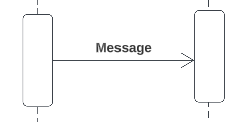
Call message
Used to call procedures, execute operations. One end of the arrow always touches the control focus or lifeline of the client object that triggers the message. The tip of the arrow points at the lifeline of the object that receives the message and takes action as a result. Call message can be either synchronous or asynchronous.
Synchronous message
 Message that is synchronous is depicted with a filled arrow. When the client sends a message, for example, to the server and waits for a response before doing anything else.
Asynchronous message
 Message that is asynchronous is depicted with a regular arrow, When the client client continues to perform operations without waiting for a response.
Return message
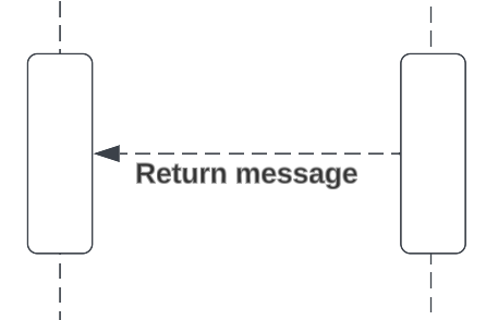 Return message represents the transfer of information to the caller of the corresponding message. Return messages are always represented by dashed lines.
Self-message
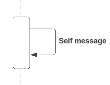 Self message is where a participant sends a message to itself.
Recursive self-message
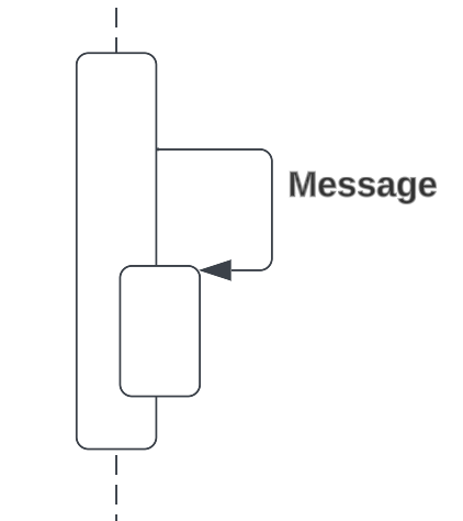 Recursive message represents reflects a new process or method invoked within the calling lifeline’s operation. It’s target point to an activation on top of the activation where the message was invoked from.
Destroy message
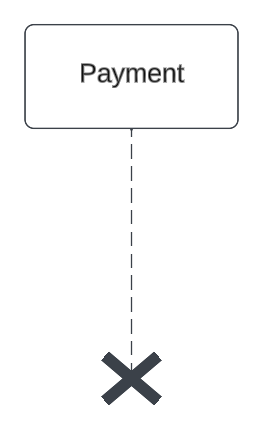 The participant’s destruction is indicated by a X sign pointing from the participant that initiates the destruction towards the one that is going to be destroyed.
If the X is drawn at the end of the participants’s life line, and there is no arrow from another object, then the object destroys itself.
The participant’s destruction is indicated by a X sign pointing from the participant that initiates the destruction towards the one that is going to be destroyed.
If the X is drawn at the end of the participants’s life line, and there is no arrow from another object, then the object destroys itself.
Guards
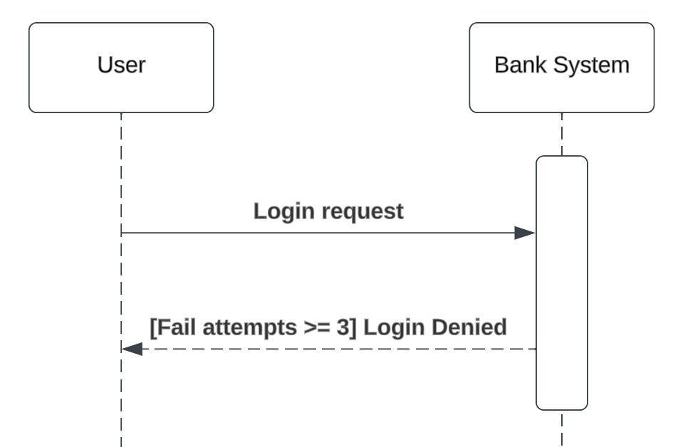 Guards are conditions that need to be used throughout UML diagrams to control flow. A guard can only be assigned to a single message. A guard element is in front of a message name and denoted with square brackets.
Guards are also used in sequence fragments.
Guards are conditions that need to be used throughout UML diagrams to control flow. A guard can only be assigned to a single message. A guard element is in front of a message name and denoted with square brackets.
Guards are also used in sequence fragments.
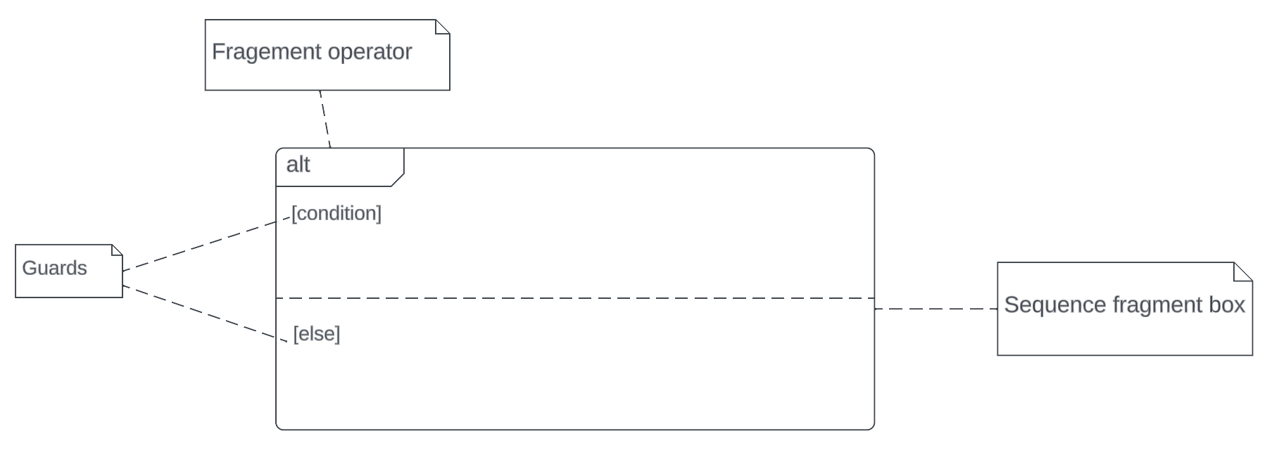
Sequence fragments
| Frame operator | Meaning |
|---|---|
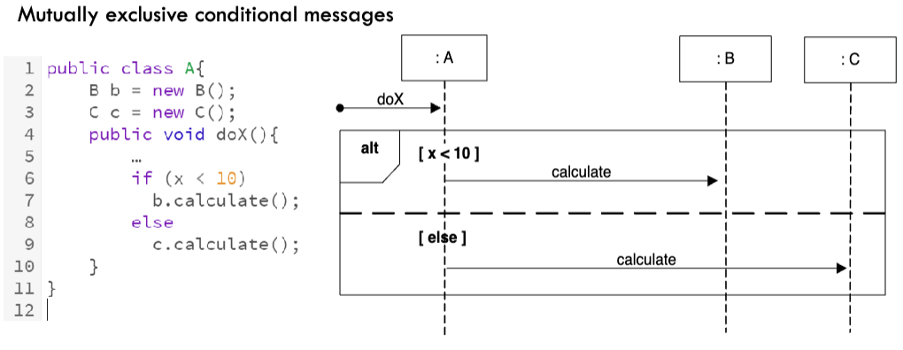
| Alt | Alternative fragment for mutually exclusion conditional logic (only one condition will execute) |
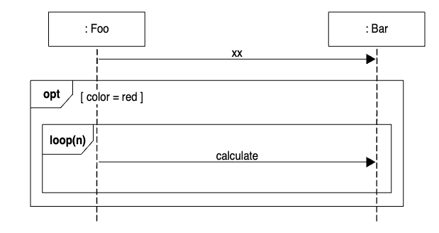
| Loop | Loop fragment while guard is true |
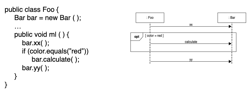
| Opt | Optional fragment that executes if guard is true |
| Par | Parallel fragments that execute in parallel |
| Region | Critical region within which only one thread can run |
 |
Optional frame
Alternative frame
Nested frame
Note (comment)
 Gives the ability to attach notes to elements. A comment carries no semantic force, but may contain useful information.
Back to parent node: UML Diagrams